


ABB Tmax T-Series Model Overview and Technical Specifications:
T5, T6, and T7 are three main models in the ABB Tmax T-Series, covering medium to high current applications from 400A to 1600A. They share a modular design philosophy and a unified accessory system, and are widely used in industrial power distribution, motor protection, new energy, and special high-voltage applications.
| T5 Series: The King of High-Performance Size Ratio |
||
| The T5 is the most well-rounded model in the Tmax series, achieving extremely high breaking capacity within a compact size, with rated currents covering both 400A and 630A levels. |
||
| Parameters | T5 400 | T5 630 |
| Frame current (Iu) | 400 A | 630 A |
| Extreme number | 3P / 4P | 3P / 4P |
| Rated insulation voltage (Ui) | 1150 V AC | 1150 V AC |
| Rated impulse withstand voltage (Uimp) | 8 kV | 8 kV |
| Rated operating voltage (Ue) | Maximum 1150 V AC / 1000 V DC | Maximum 1150 V AC / 1000 V DC |
| Division ability (ICU) | 415V AC: up to 200 kA 690V AC: 80 kA 1000V AC: 20 kA 1150V AC: 12 kA |
415V AC: up to 200 kA 690V AC: 50 kA 1000V AC: 20 kA 1150V AC: 12 kA |
| Use category | Class B (400A) / Class A (630A) | Category A |
| Mechanical life | 20,000 times | 20,000 times |
| Number of operations per hour | 120 times | 120 times |
| External dimensions (W×D×H) | 140 × 103.5 × 205 mm (3P) | 140 × 103.5 × 205 mm (3P) |
| Weight (fixed) | 3.25 kg (3P) / 4.15 kg (4P) | 3.25 kg (3P) / 4.15 kg (4P) |
| Trip unit options |
||
| The T5 supports multiple types of trip units, allowing for flexible selection based on protection requirements: |
||
| Trip unit type | Model | Features |
| Thermomagnetic | TMD / TMA | Overload and short-circuit instantaneous protection, economical and reliable, suitable for AC/DC systems. |
| Electronic | PR221DS | Basic electronic protection, LSI function |
| Electronic | PR222DS/P | Power distribution protection, LSI or LSIG, with current measurement |
| Motor protection | PR222MP | Integrated overload, short circuit, phase loss, and locked rotor protection |
| Installation method: |
| Fixed (F): Standard configuration Insert (P): T5 400 optional Retractable (W): T5 400 optional |
| Terminal Block Options: |
|
Front Terminal Block (F) Copper Cable Front Terminal Block (FC Cu) Copper/Aluminum Cable Front Terminal Block (FC CuAl) Extended Front Terminal Block (EF) Extended Front Terminal Block (ES) Rear Horizontal Terminal Block (HR) |

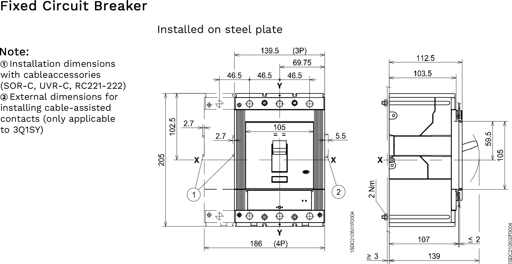
| Dimensions (mm) |
| TmaxT5 - Fixed |
 |
| Dimensions (mm) |
| Tmax T5 - Insertion-Type |
 |
| Dimensions (mm) |
| TmaxT5 - Pull-out |
 |
| T6 Series: High Current Compact Circuit Breaker | |||||||||||
| The T6 increases the rated current of the Tmax series to the 800A-1000A level, while maintaining the same 103.5mm depth as the T4/T5, achieving a high degree of uniformity. | |||||||||||
| Parameters | T6 630 | T6 800 | |||||||||
| Frame current (Iu) | 630 A | 800 A / 1000 A | |||||||||
| Extreme number | 3P / 4P | 3P / 4P | |||||||||
| Rated insulation voltage (Ui) | 1000 V AC | 1000 V AC | |||||||||
| Rated impulse withstand voltage (Uimp) | 8 kV | 8 kV | |||||||||
| Rated operating voltage (Ue) | Maximum 1000 V AC / 750 V DC | Maximum 1000 V AC / 750 V DC | |||||||||
| Division ability (ICU) | 415V AC: Maximum 120 kA; 690V AC: 50 kA; 1000V AC: 12 kA |
415V AC: Maximum 100 kA; 690V AC: 40 kA; 1000V AC: 12 kA |
|||||||||
| Use category | Category B | Category B | |||||||||
| Mechanical life | 20,000 times | 20,000 times | |||||||||
| Number of operations per hour | 120 times | 120 times | |||||||||
| External dimensions (W×D×H) | 210 × 103.5 × 268 mm (3P) | 210 × 103.5 × 268 mm (3P) | |||||||||
| Weight (fixed) | 9.5 kg (3P) / 12 kg (4P) | 9.5 kg (3P) / 12 kg (4P) | |||||||||
| Trip unit options | |||||||||||
| The T6's trip unit system is highly consistent with that of the T4/T5, and also supports configurations with higher current ratings. | |||||||||||
| Trip unit type | Model | Applicable current | Features | ||||||||
| Thermomagnetic | TMA | 630A / 800A | Adjustable thermal-magnetic protection, suitable for AC/DC. | ||||||||
| Electronic | PR221DS | 630A / 800A | LSI Electronic Protection | ||||||||
| Electronic | PR222DS/P | 630A / 800A | LSI or LSIG power distribution protection | ||||||||
| Motor protection | PR222MP | 630A | Dedicated motor protection with thermistor input | ||||||||
| Installation Methods |
|
Fixed (F): Standard Configuration Retractable (W): 630A and 800A Optional |
| Terminal Block Options |
|
Front Terminal Block (F) Copper Cable Front Terminal Block (FC Cu) Copper/Aluminum Cable Front Terminal Block (FC CuAl) Rear Terminal Block (R) Rear Horizontal Terminal Block (HR) |

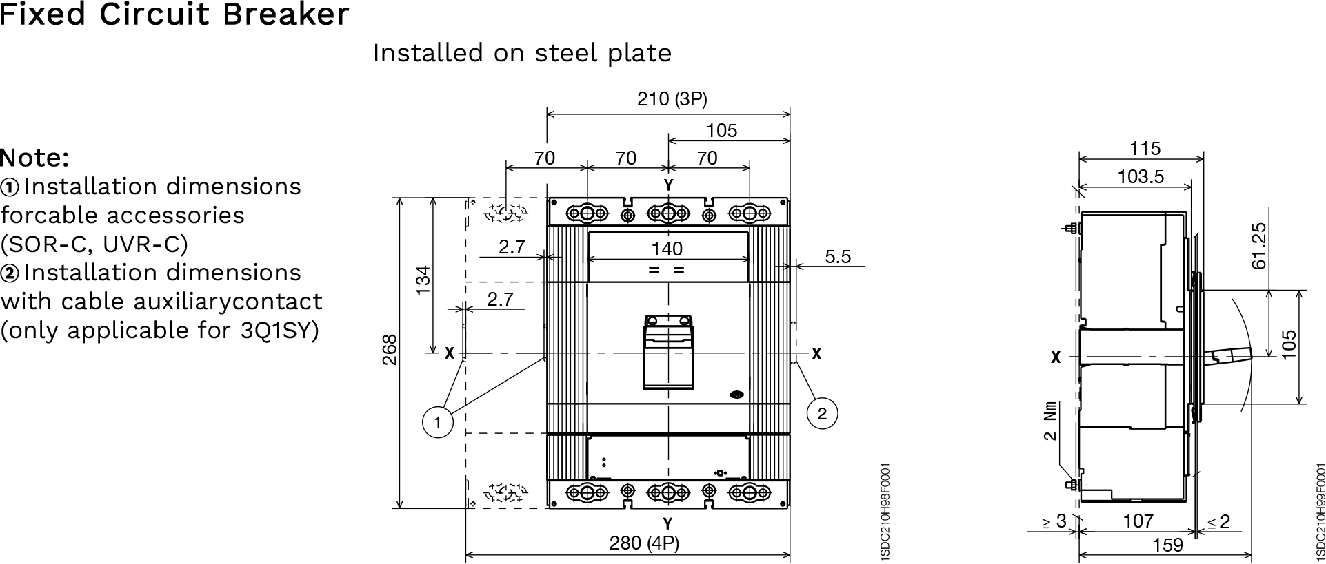
| Dimensions (mm) |
| TmaxT6 - Fixed |
 |
| Dimensions (mm) |
| TmaxT6 (630A-800A) - Pull-out |
 |
| T7 Series: Flagship Molded Case Circuit Breaker | |||||||||||
| The T7 is the flagship model in the Tmax series, with rated currents ranging from 800A to 1600A, filling the gap between molded case circuit breakers and air circuit breakers. The T7 boasts more powerful functions and more flexible installation options. | |||||||||||
| Parameters | T7 (800-1600A) | ||||||||||
| Frame current (Iu) | 800 / 1000 / 1250 / 1600 A | ||||||||||
| Extreme number | 3P / 4P | ||||||||||
| Rated insulation voltage (Ui) | 1000 V AC | ||||||||||
| Rated impulse withstand voltage (Uimp) | 8 kV | ||||||||||
| Rated operating voltage (Ue) | Up to 690 V AC | ||||||||||
| Division ability (ICU) | 415V AC: Maximum 150 kA 690V AC: 60 kA |
||||||||||
| Use category | Category B | ||||||||||
| Mechanical life | 20,000 times | ||||||||||
| Number of operations per hour | 60 times | ||||||||||
| Trip Unit Options – Intelligent Electronic Trip Unit | |||||||||||
| One of the highlights of the T7 is its advanced electronic trip unit, available in two models: basic and advanced. | |||||||||||
| Trip unit model | Type | Core Functions | |||||||||
| PR231/P | Basic type | DIP switches set protection thresholds, and LEDs indicate the fault type. | |||||||||
| PR232/P | Basic type | DIP switch settings support more protection functions | |||||||||
| PR331/P | Advanced | Equipped with a rated current connector, the rated current can be changed by replacing the connector, and an LCD display screen. | |||||||||
| PR332/P | Advanced | Wide-range LCD display with data logger function, capable of recording all events and electrical values for easy fault analysis. | |||||||||
| Advanced Features |
|
Rating Module: PR331/PR332 allows changing the circuit breaker's rated current In by replacing the module, without replacing the entire circuit breaker. Data Logger: PR332 records historical events and electrical parameters for easy maintenance and analysis. |
| Installation Methods |
|
Fixed (F): Standard configuration, supports vertical/horizontal installation Retractable (W): Optional, equipped with a new swing-out system for quick and safe operation |
| Mechanical Characteristics |
|
Manual Operation: Standard toggle handle Electric Operation: Optional electric operating mechanism Mechanical Interlocking: Supports mechanical interlocking between two T7 circuit breakers or between a T7 and an air circuit breaker via a flexible cable. |
| Terminal Options |
|
Front Terminal Blocks Rear Horizontal Terminal Blocks (HR) Rear Vertical Terminal Blocks (VR) Extended Front Terminal Blocks (EF/ES) |

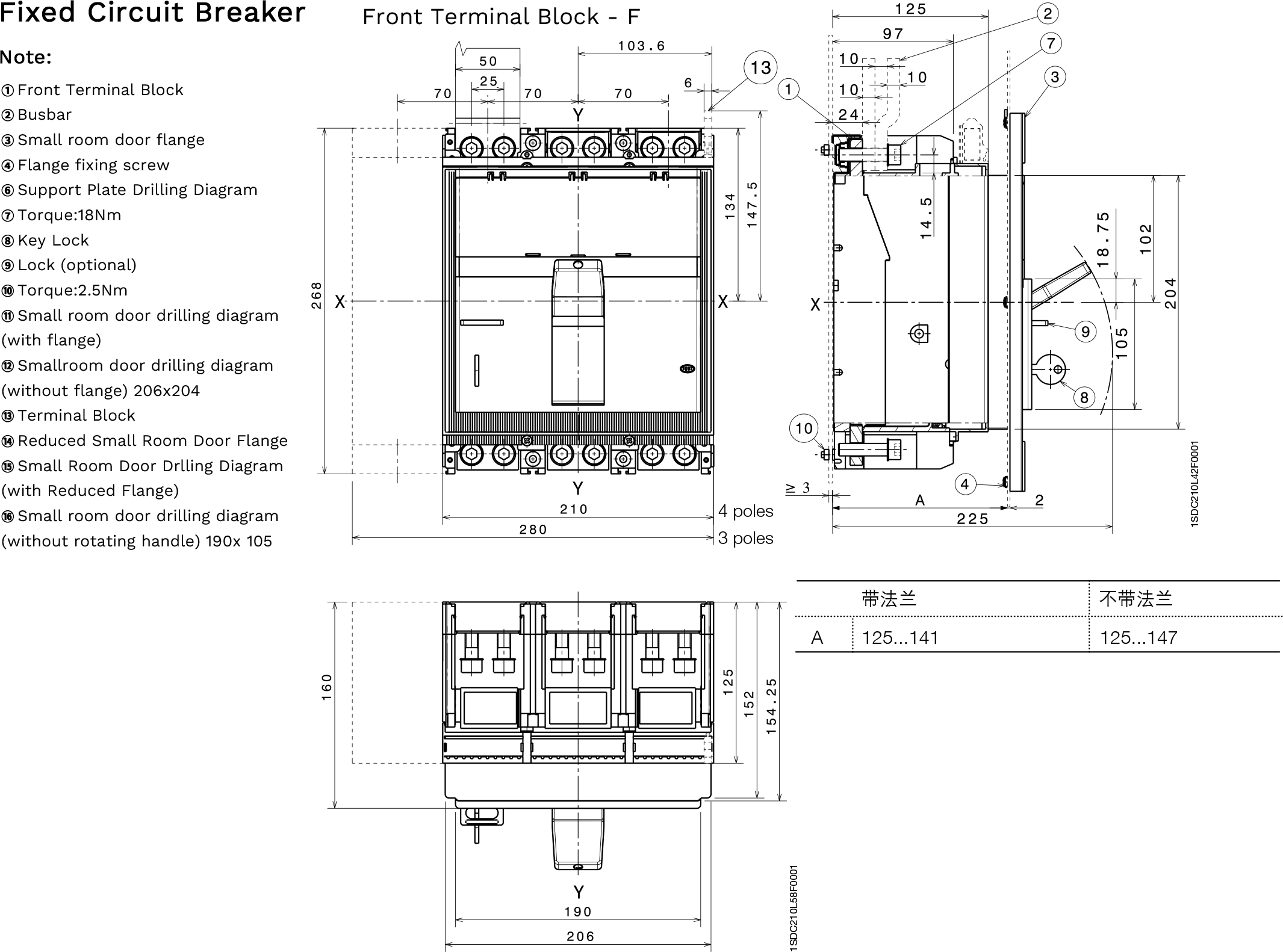
| Dimensions (mm) |
| TmaxT7 - Fixed |
 |
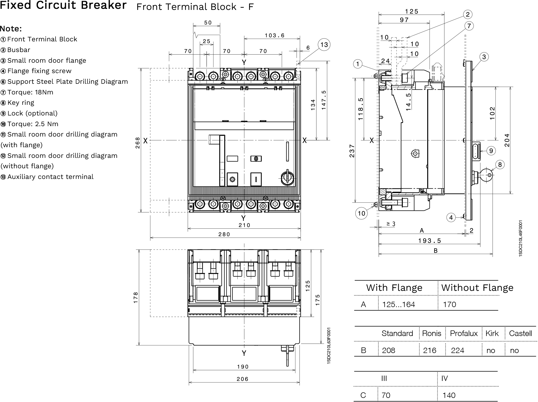
| Dimensions (mm) |
| Tmax T7M - Fixed |
 |
| Dimensions (mm) |
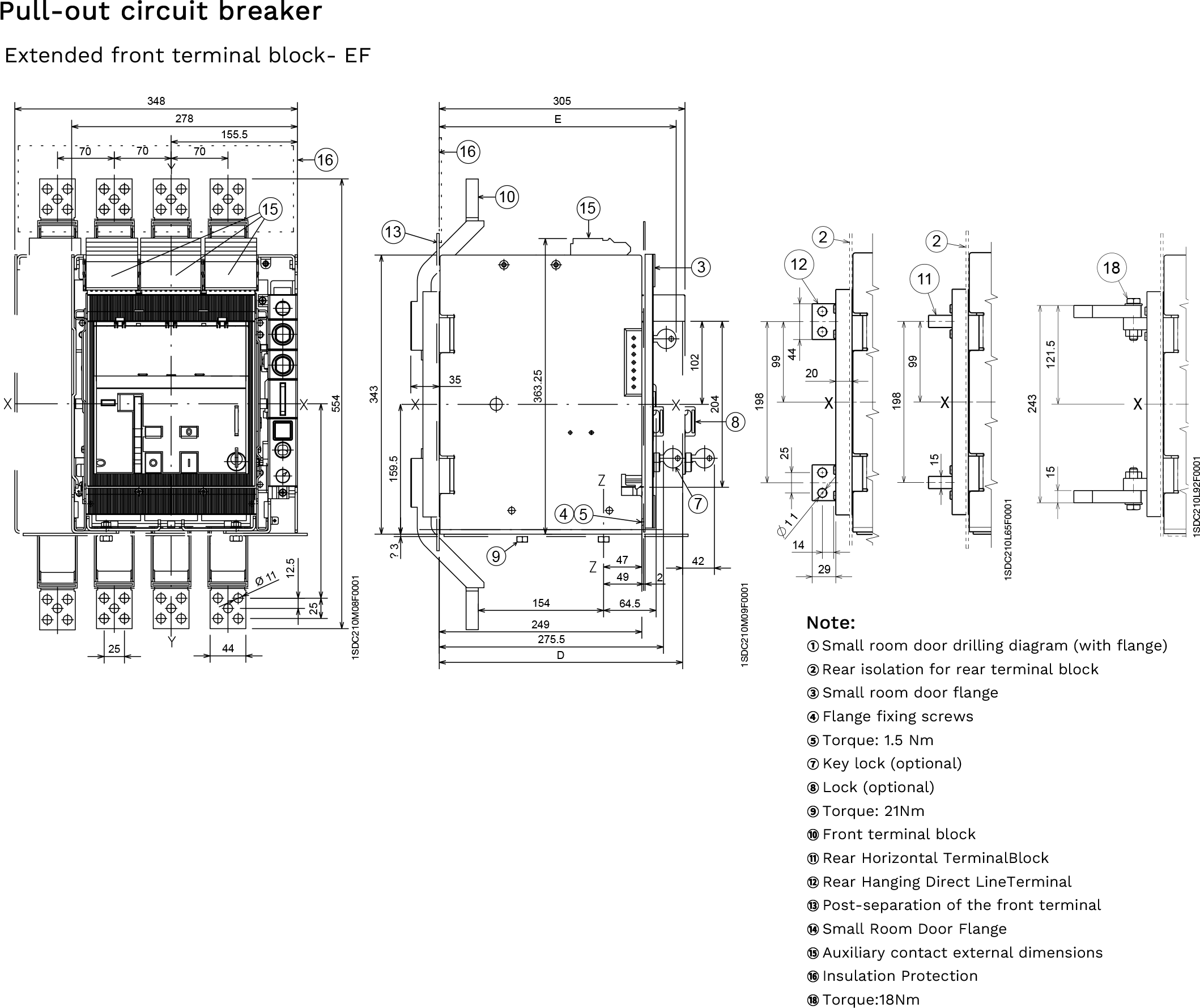
| Tmax T7 - Pull-out |
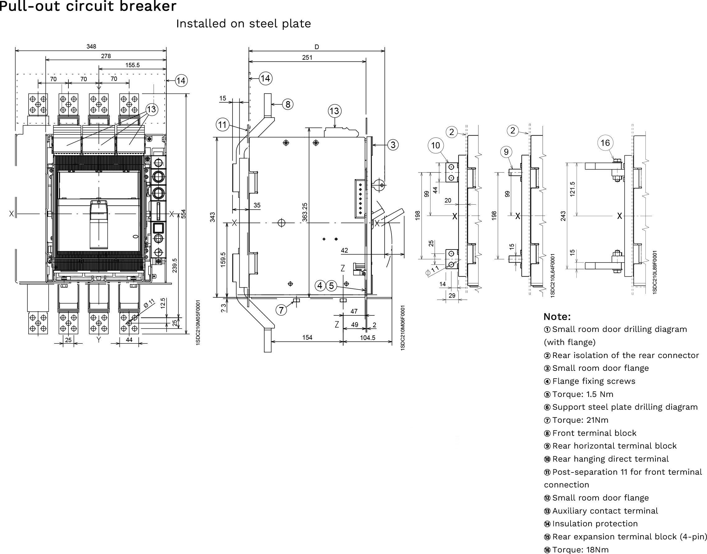 |
| Dimensions (mm) |
| Tmax T7M - Pull-out |
 |
| Comparison Summary of Three Models | |||
| Comparison Dimensions | T5 | T6 | T7 |
| Current range | 400A, 630A | 630A, 800A, 1000A | 800A, 1000A, 1250A, 1600A |
| Maximum splitting capacity (415V) | 200 kA | 120 kA | 150 kA |
| Special voltage capability | 1150V AC / 1000V DC | 1000V AC / 750V DC | 690V AC standard |
| Unified Depth | 103.5 mm | 103.5 mm | Larger (not uniform) |
| Trip unit type | Thermal/Magnetic/Electronic/Motor Protection | Thermal/Magnetic/Electronic/Motor Protection | Electronic (PR23x/PR33x) |
| Pull-out optional | T5 400 optional | Optional | Optional |
| Applicable Scenarios | Industrial power distribution, high voltage special applications | High-current power distribution and motor control center | Main incoming switch, critical power supply, and electric operation scenarios |
| Application scenario suggestions | |||||||||||
| Model | Recommended application scenarios | ||||||||||
| T5 | Main switches for industrial power distribution cabinets, high-voltage special applications (such as 1150V AC/1000V DC mining and tunnel lighting), and input/output protection for frequency converters. | ||||||||||
| T6 | High-capacity distribution cabinets, motor control center (MCC), generator protection, 690V industrial systems | ||||||||||
| T7 | Low-voltage incoming main switch, upstream and downstream protection systems in conjunction with air circuit breakers, applications requiring electrically operated operation, and critical power supply systems requiring data recording and analysis. | ||||||||||